
Advantages of Solid State Relays, (SSR) from Root2 Ltd
THINGS TO CONSIDER WHEN USING SOLID STATE RELAYS
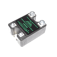
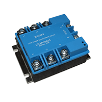
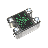
SOLID STATE RELAYS
Solid state relays have been around for many years and offer a very reliable long term alternative to electro-magnetic relays and contactors, effectively reducing the requirement for regular maintenance. Their sealed construction and lack of moving parts or contacts makes them the obvious choice for use in harsh environments and they will also withstand substantial vibration and 'G' forces. +
The control signal can be very small, (3 to 32 volts dc @ <20mA) and switching typically takes place within one half cycle of the supply line voltage making them ideal for use as a fast reliable interface between logic circuits, (such as computers) and high power electrical loads. The use of Thyristor switching components is particularly cost effective for fast systems and for switching inductive loads, i.e. transformers and heaters, whose resistance changes with temperature or time. However a Thyristor will only conduct when the applied voltage across it is greater than 2 volts and this 'cut-off' is what produces the pulse of noise every half cycle. Solid state relays which are described as operating at the 'zero crossing' point actually do so at the + and -2volt points - 'random' switching occurs at any part of the ac cycle.
SUPPRESSION OF RF
Because Solid state relays switch large amounts of power, both they and the electrical apparatus they are a part of will produce significant levels of noise, (typically 120db for a Thyristor-switched device and higher still for Triacs). The European EMC Class B limits for conducted noise, (EN55022) are set at 66/56db, (quasi-peak) and 56/46db,(average) and this means that substantial suppression or filtration of the noise must be added to any electrical circuit which employs standard solid state relays. +
Without filters the resultant high levels of harmonic noise in the applied voltage can cause over-heating and subsequent reduction in the life of capacitors and motors which are directly on line. Solid state relays used for switching electrical services in new buildings within the EU will also require EMC filters. In accordance with the EU EMC Directive the solid state relay is classed as a component which produces and is susceptible to electrical noise - manufacturers of these components will now be required to issue design guidelines for installers and users to ensure that the correct EMC filter is used to achieve compliance. Most SSR manufacturers are content to leave the problem of EMC compliance to the designer/manufacturer of the end product whereas Root2 Limited takes the view that their low noise solid state relay should be EMC compliant in its own right. The Root2 relay is also designed with built in immunity to external sources of RFI and has been certified to be in compliance with EN50082-2 (1995) and EN61000-3-2 standards.
EMC LINE FILTERS FOR USE WITH SOLID STATE RELAYS
EMC filters consist of a series of passive 'LC' elements that must be capable of passing the rated line current without saturating and over-heating. Because of the ferrite/iron materials used for the chokes and the physical size required to avoid saturation, filters tend to be very large and expensive items which introduce additional problems of circuit complexity, weight, heat dissipation and reliability. +
EMC filters use large capacitors that may cause RCD devices to trip due to earth leakage currents. The leakage current may also cause problems in meeting the requirements for VDE portable equipment and UL544 non-patient medical equipment. The filter capacitors are connected between phase and earth and may remain charged for some time after the removal of the supply which is a safety hazard. EMC filters are designed to work with ac supplies that are balanced with respect to earth. To be effective the EMC filter must be fitted as close as possible to the source of RF noise (solid state relay) which may interfere with airflow and cause problems of over-heating. Ready-made, EMC line filters which will operate above 50amps and which will effectively remove the typical low frequency noise produced by a solid state relay are very difficult to find and manufacturers of electrical apparatus are usually faced with the task of designing their own filter circuits and putting the completed assembly through extended EMC compliance testing. Electrical contractors installing new building services will also have to consider the size and complexity of their switch panels if EMC filters are incorporated.
SAFETY CONSIDERATIONS
Solid state relays use semi-conductor output devices, (back-to-back thyristors) and ultra-fast semiconductor fuses must be used to give maximum protection against surge currents resulting from short-circuit conditions in the load or wiring. This type of fuse will not provide protection against sustained medium overload conditions and a standard HRC fuse or suitable circuit breaker should also be fitted in the supply line. +
The solid state relay is NOT an effective means of circuit isolation due to small leakage currents through the SSR internal circuitry and possible fault condition break-down in the thryristors themselves. It is vital therefore that a means of totally isolating the relay and its associated circuit/load be incorporated and safe working practice followed.